When it comes to performance and robustness, the SKYPER 12 und 42 LJ drivers deliver what it takes for use in SiC inverter solutions of up to 100 kHz. With 7kV burst immunity and 8 million hours of reliable operation, these drivers will ensure your system is both reliable and stable in field application.
In 2016, the market for power electronics had a turnover of more than 30 billion US dollars (Source: IHS). Today, this market is covered almost exclusively by silicon-based power electronics. New challenges with regard to integration level, efficiency or switching frequency requirements, can stretch silicon-based power electronics to their limits. Integrated inverter solutions must ensure minimum self-heating by the power electronics, new power supplies have to be downsized by almost 50% in terms of physical size and switching losses, and new system approaches call for high frequencies in order to reduce the number of passive components or boost overall system performance. Today, in many areas, alternative inverter topologies such as multilevel or interleaved systems are being used to boost efficiency and performance. Here, new materials such as SiC, GaN or Ga2O3 can help minimize system complexity and, subsequently, control requirements, while enhancing system performance at the same time.
Silicon carbide, which has been an important research focus for the past 15 years, is one the most advanced technologies in this area. According to market research institutes, the market for silicon carbide can be expected to grow by some 20% a year until 2025 (Source: Yole). This is reason enough to take a closer look at the challenges that arise when this technology is used in practice. SiC can be used for applications ranging from 600V up to 25kV. The major technological advantage that SiC has over silicon is its high switching frequencies and the low switching losses, which is allowed by the MOSFET structure.
The efficient use of this technologyresults in increased requirements for the periphery devices. To keep losses to a minimum, faster switching frequencies are needed and the module designhas to allow for a low-inductance DC link connection. Driver electronics are expected to be increasingly compact yet have more output power and are expected to switch faster but need better interference immunity.
For gate drivers in SiC inverters to be efficient, the switching behaviour of the new technology has to be examined more closely. The first challenges identified are usually application-related conditions such as turn-off behaviour across the entire temperature range or operation in real EMI environments. At present, the main criterion for the use of SiC MOSFETs is the potential to reduce switching losses. Using driver electronics, this effect can be enhanced significantly by reducing gate resistances and delay times.
")
Hybrid SiC power electronic modules, i.e. a fast-switching silicon-based IGBT with an efficient SiC Schottky diode, do not need special driver electronics. SiC MOSFETs, in contrast, require more of the driver. The SiC generations available today need different gate voltages, ranging from -3V to -5V for turn-off and +15V to +20V for turn-on. The aim for future chip generations is to have a standard voltage of +15V/-5V like Si chips.
SiC has higher electron mobility and, owing to the higher dielectric strength, allow for far thinner chips, which means less resistance per surface area. This goes hand in hand with the ratio of falling turn-on resistance to gate voltage increase. The change in resistance reaches saturation at voltages over 18V. This effect also leads to a change in the gate charge curve (Miller plateau) of SiC MOSFETs across the entire temperature and current range. Future chip generations aim to limit this effect to a voltage level of 15V.
Depending on the current and temperature, the miller plateau can lie between 3V and 16V. To prevent unintentional switching states, the driver electronics has to supply a gate voltage of more than 18V to ensure safe turn-on at zero tolerance. SEMIKRON meets this requirement using secondary-side voltage control, ensuring the reliable supply of non-temperature-dependent turn-on gate voltage.

The higher gate voltage causes another effect. The drain current is roughly proportional to (UG-UTH)². This means the higher gate voltage results in a larger short-circuit current that can be as much as ten times the rated current for silicon-based IGBTs. Additional gate clamping can help avoid this increase in gate voltage and the resultant increase in short-circuit current.
In addition to this, SiC MOSFETs are smaller and have a lower thermal capacity at increased short-circuit currents. As a result, SiC MOSFETs have lower short-circuit capability. Standard silicon-based IGBTs lie in the region of 6-10µs, plus a small safety margin in today’s chip generations. SiC MOSFETs, on the other hand, lie in the region of 3-5µs, depending on the manufacturer. Future generations are expected to have values that exceed 5µs. The level of voltage overshoot during turn-off can be achieved with various measures such as gate voltage reduction or multistage turn-off algorithms. The major challenge here, for the driver electronics is to detect the error condition and react to it quickly enough. In other words, for short-circuit detection to be efficient it has to detect the overcurrent quickly to prevent thermal overload and slow down the turn-off process, preventing the drain source voltages from getting too high.
In SEMIKRON‘s SKYPER drivers, short circuits are detected by comparing the VDS voltage with a dynamic reference line. The boundaries are adjusted to the given module by altering the blanking time and trigger threshold. The high-voltage diode and the series resistor have defined offset voltages with low tolerance values. The bandwidth, so the speed of detection, can be adjusted irrespective of the input impedance. In this way, in the event of a very fast, low-inductance short circuit, the driver will respond without any blanking time. In the event of strong voltage changes, the diode will stop conducting, the filter capacitor CI is charged, and the driver electronics can respond within less than 1µs, depending on the filter design. In this case, the SKYPER driver family switches off softly with a separate SoftOff output stage with resistance values in the region of 15-40Ohm. That means around twenty times the standard gate resistance, in doing so reliably avoiding overvoltages or critical oscillations.
When defining the trigger threshold, it must be considered that the saturation voltage increase is more or less linear and cannot be compared with that of the Si-IGBT collector-emitter saturation voltage. What is more, the conducting-state voltages per SiC chip area are generally lower than those for silicon-based chips. Depending on the module/chips, efficient short circuit triggering thresholds will lie in the region of 2-4V in contrast to 6-8V for IGBT solutions.

Another challenge are the switching thresholds. Compared with silicon-based IGBTs, SiC MOSFETs have lower threshold voltages of around 3V and a higher temperature coefficient than the IGBTs.
At normal operating temperatures and higher di/dt rates, this results in the risk of the gate voltage being increased unintentionally owing to coupling effects. This applies to both normal switching situations and short-circuits. Two measures can help combat this, one being a low-inductance gate path, the other being gate clamping.
On top of this are incoupled gate currentswhich can further decrease the negative gate voltage, possibly damaging the chip due to the thin gate oxide layer. SEMIKRON drivers include safety features such as optional gate clamping on the adapter boards for its SKYPER driver cores or active gate clamping in highly integrated IPMs such as SKiiP4. The gate voltages are adjusted by shifting the source potential. The Zener diode limits the negative gate voltage to -5V and adjusts the positive gate voltage to over 18V. The resistance defines the current flow and prevents a voltage dip. This is an efficient, cost-effective and robust driver solution for the latest SiC power modules and is used in various SEMIKRON modules and drivers such as SKYPER 12 or SKYPER 42 LJ for applications ranging from 20kW to as much as 250kW.

Another challenge that arises is the stray inductances of the module cases. In combination with the chip capacitances, these form resonant circuits in the gate path, leading to various coupling effects.Inductance in the gate path will reduce the rate of rise of current in the gate driver electronics, in doing so slowing down the gate charging and discharging process. Once a certain saturation level has been reached, this effect is reversed and the energy stored in the gate paths speeds up turn-on.
Owing to the low gate resistances, which are needed to switch the fast SiC chips, the resistance in this resonant circuit does not damp anymore. This calls for a very low-inductance driver circuit and optimized gate resistances in terms of over voltages cross the entire temperature range versus losses.
In the SiC modules available today, these internal stray inductances often limit the maximum rate of rise of current, restricting the switching frequency to around 100kHz. For the driver electronics, the fact that the gate capacitance of SiC MOSFETs is comparable with that of silicon-based IGBTs must be taken into account. The gate current required for the power electronic components is calculated as the product of the gate capacitance and the switching frequency. Thus, an increase in the switching frequency from 10kHz for a 300A Si IGBT module to 50kHz for a SiC module means 400% more gate drive power is needed. This considerable increase in power means that new methods are required with regard to heat dissipation and efficient gate control. This is vital if the positive trend towards increased power density is not to be cancelled out by the need for driver electronics that are double their size.

After all, the higher rates of rise for voltage and current as well increasingly compact inverter designs result in far greater electromagnetic influences that act on the driver electronics. To make sure that this trend does not mean that reliable signal processing and system robustness get left behind, it is important to explore new ways of optimizing electromagnetic compatibility. Driver electronics ought to be designed for a du/dt rating of 100kV/µs and interference-free operation at a field strength of 30V/m. From a certain switching frequency level on, differential interfaces are an absolute must. SEMKIRON SKYPER signal transformers feature an optimized design based on core segment windings and special-purpose insulating material and boast low coupling capacitance and rectangular signal transmission. Thanks to innovative electromagnetic shielding and optimized filter and mass concepts, SKYPER driver electronics also work reliably in high integration level SiC inverters.
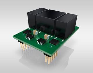
SEMIKRON‘s SKYPER 12 and SKYPER 42LJ are efficient SiC drivers featuring adapter boards for 17mm, 62mm and MiniSKiiP modules. This PBC-based solution also allows for an ultra-low-inductance DL link bus design. SKYPER drivers use highly integrated ASICs solutions that ensure reliable field operation, delivering a burst immunity of 7kV and 8 million hours of reliable operation in the field. The separate softOFF output stage, reliable gate clamping, and precise gate voltage control ensure the SiC MOSFETs are operated both safely and reliably in any situation. The fast-mode VDS detection and the adjustable filter management likewise meet the performance requirements and ensure efficient SiC chip operation up to 100kHz.
Regardless of the integration level, Moreover, SEMIKRON has the right SiC solution for any application, from efficient hybrid SiC modules in 17mm cases to full SiC solutions in a variety of housings and highly integrated SiC stacks. This is the foundation needed for SiC technology to finally get off the ground.